Building a room model from scratch (PDF)
The following hands-on tutorial contains step-by-step instructions for creating new rooms and adding different materials to it. Please note, that there are several options to model projects in EASE 5. This tutorial does not contain all options. Please see helpful information and shortcuts for any Tool in EASE 5 by hovering over the corresponding button.
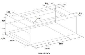
Room plan
The room plan serves as a basis for the drawing of the new project.
Step by step instructions
Create a new project
- Select FILE and choose the NEW button (Ctrl+N)
- Add Project Name: Meeting Room
- SAVE AS: Meeting Room (F12)
Create room volume
In the SURFACES tab, select POLYGON (Ctrl+P), then:
- Type 6 and press Enter
- Type Y, then -18 and press Enter
- Type -12 and press Enter
- Type Y, and click on the first created vertex. A vertex with restricted X with the same Y coordinate as the first vertex will be created.
- Click again on the first vertex. The Face now will close.
Hit ESC to escape the POLYGON tool. Your Face should now have the following coordinates:
| X | Y | Z | |
| 1st Vertex | 6 | -18 | 0 |
| 2nd Vertex | 6 | 0 | 0 |
| 3rd Vertex | -6 | 0 | 0 |
| 4th Vertex | -6 | -18 | 0 |
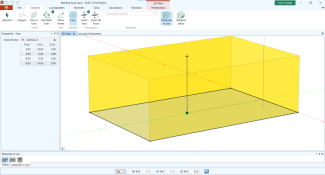
Extrude the face
- Select EXTRUDE FACE in the SURFACES tab (Ctrl + E)
- Click anywhere or just press Enter to define the ancor point for the extrusion
- Type 6, and hit Enter again. Your face has now been extruded to the Z coordinate 6.
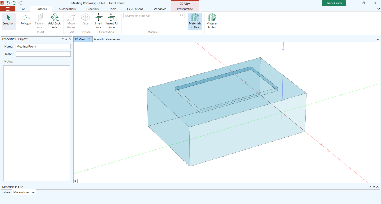
Create ceiling coffer volume
- Use the POLYGON Tool and enter the first vertex with
- Tab, 3.5, Tab, -3, Tab, 6, Enter
- Y, -12, Enter
- X, -7, Enter
- Y, double click on the first created vertex
- Extrude it by 0.5 the same way you extruded the face of room base
- Delete the Bottom Face of the ceiling coffer by selecting it and hitting the Delete key
To select it, hover the top face of it, hold Ctrl key, and scroll the mouse wheel until you reach the face - Now create the ceiling opening by first selecting the Ceiling Face
- Select the FACE IN FACE option in the SURFACES tab (Ctrl+Alt+W)
- Re-Draw the coffer bottom, select it and then delete it. Your mouse will automatically snap to vertices when getting close.
Generate more faces
Since rooms very often consist of faces with different materials, we will now split some of the faces to get a more realistic room.
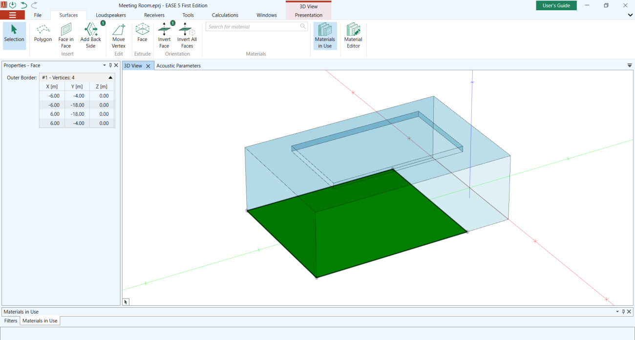
Split the floor face. Start at the first corner of the floor (located at -6, -0, 0) and draw a face 4 m deep:
- Select the floor face and choose FACE IN FACE
- Click the first vertex, type Y, -4, and Enter to insert the second vertex
- Type X, 12, Enter for the third vertex
- And Y, 4 for the fourth one.
- Click the first vertex again, or press C, to close the face
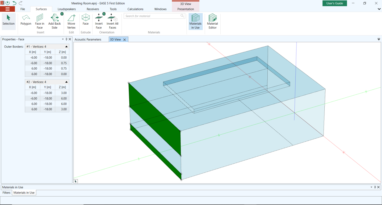
Add a wall panel:
- Select the face of the long, far wall and choose FACE IN FACE
- Click on the upper right corner
- Type Z and -3, and Enter
- Type Y and -18
- Click on the existing vertices to close the face
Repeat the same on the left short wall:
- Start FACE IN FACE for this wall
- Type Z, 3
- Type Shift+Z and select the opposite wall (it will automatically snap to it)
- Type Z, -2.25
- Type X and click on the first vertex
- Finally, close the face
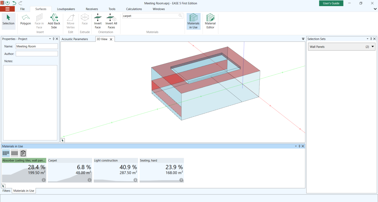
Assign Materials
To obtain the same results as in this tutorial, please use materials only from the Generic Materials section.
Change the Default Material:
- Open the MATERIALS IN USE window by clicking on the button in the SURFACES tab (Ctrl+Shift+M)
- In the SURFACES tab, under MATERIALS, search for the Material Light Construction by typing it in the Search Bar and click on it
- Change all faces to Light Construction by clicking on the tile of the Default, 100% reflective material in the MATERIALS IN USE window
Wall panels:
- Escape to go back to the Selection cursor
- Select both wall panels
- Go to TOOLS and select STORE SELECTION
- Change label to Wall Panels
- Change material to Absorber (ceiling tiles, wall panels)
- If both wall panels where not selected anymore, double click on the SELECTION SET
Ceiling:
- Select main ceiling (perimeter)
- Change material to absorber (ceiling tiles, wall panels)
Floor:
- Select larger floor
- Change material to Seating Hard
- Select smaller floor
- Change material to Carpet
To get an overview of which material was used on which face, you can click on the material in the MATERIAL IN USE window. All faces with the selected material will be marked in red.
Check Room Geometry
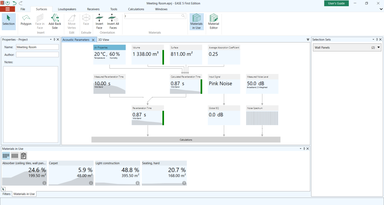
To make sure that the room entry is complete and correct, you can view some parameters in the ACOUSTIC PARAMETERS window:
- Go to the ACOUSTIC PARAMETERS window
- The color next to the Volume Tile indicates if your room is closed and if all faces are orientated correct. If the color is yellow or red, please the our FAQ: How can I close holes in my (imported) model?
- You can also observe different parameters of your room, such es the Average Absorption Coefficient, the Calculated Reverberation Time (Eyring Formula), the Input Signal and the Noise Level. Several Parameters can be edited by clicking the tiles.